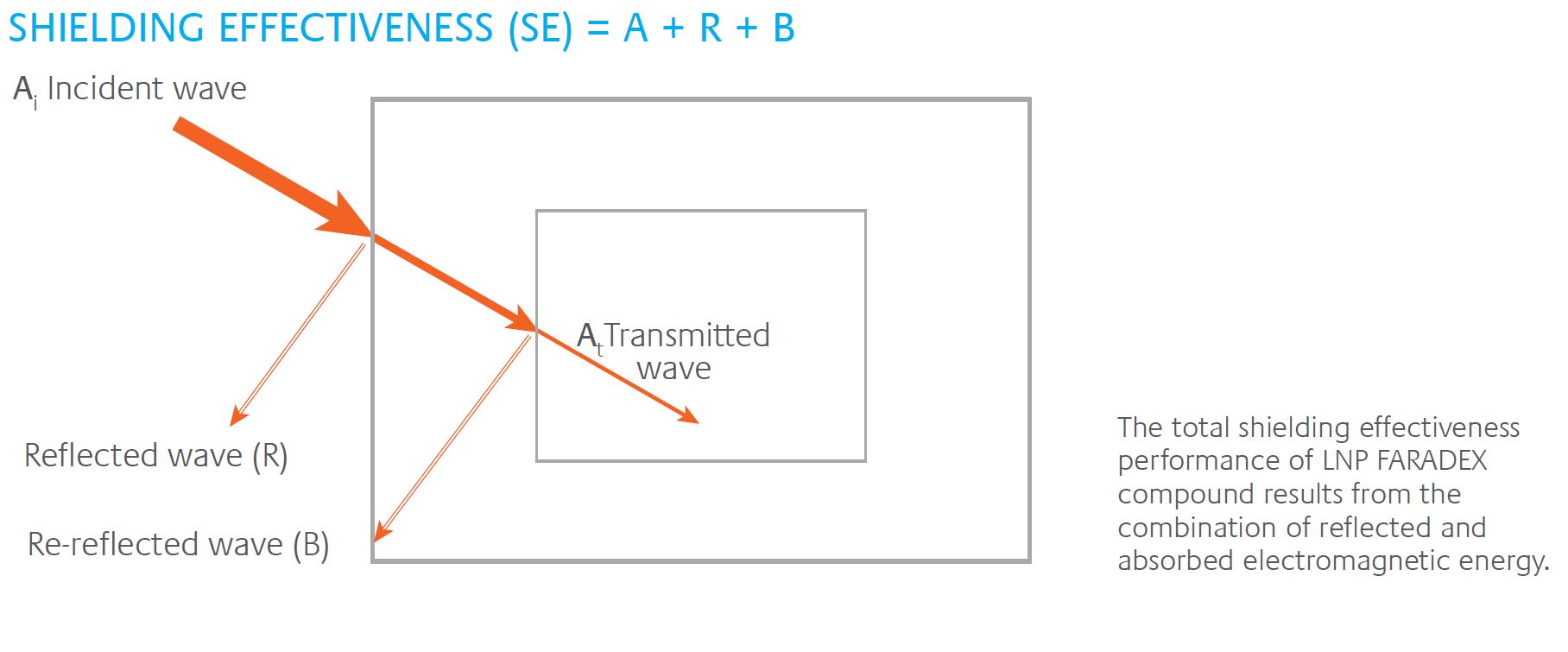
LNP™ FARADEX™ COMPOUNDS FOR EMI SHIELDING
LNP™ FARADEX™ COMPOUNDS
SABIC recognizes the global customer demand for ever-smaller electronic devices with highly sophisticated functionality, and also acknowledges the engineering challenges involved to create them. Today's electronics can generate strong electromagnetic noise that can affect electromagnetic compatibility (EMC) and as a result, impact device performance.
LNP FARADEX compounds from SABIC are a potential solution to resolve electromagnetic interference (EMI) and electrostatic discharge (ESD) challenges that impact the performance of today's electronics.
AN EXCELLENT CHOICE FOR EMI SHIELDING
LNP™ FARADEX™ compounds from SABIC are conductive thermoplastic materials with properties that can save processing steps, permit exceptional design freedom for complex device geometries, and provide the optimum level of shielding for sensitive electronics.
WHERE DOES EMI COME FROM?
Ever since Marconi raised the first radio antenna, the broadcasted electrical noise from lightning storms could be heard. This phenomenon is known as radio frequency interference (RFI). Today’s frequencies at which electronic equipment operates are much higher, typically in the range of 30 Mhz to 10 Ghz. Electromagnetic Interference (EMI) is the newer term for the undesired negative effects caused by electromagnetic radiation.
EMI occurs when the electromagnetic field or transmission of one device disrupts, impedes or degrades the operation of another electronic device.
Electromagnetic disturbances can be conducted or radiated and originate from low or high frequency sources in the circuits, components and wires of electronic equipment.
The skyrocketing use and ever increasing portability of electronics has brought these devices even closer to one another, aggravating the issue. moreover, as devices become smaller, faster and more complex, their sensitivity increases, making them more vulnerable to interference. not surprisingly, regulatory standards have become more stringent, increasing the challenge faced by electronics, packaging and compliance engineers.
The shielding properties of LNP™ FARADEX™ compounds make them an excellent choice for sensitive applications where high performance is a must.
APPLICATIONS
- healthcare diagnostic and monitoring equipment
- Industrial test and measurement equipment
- Telecommunication infrastructure devices
- Wireless communication asset tracking devices
- Security including products, like Closed Circuit TV cameras
- Consumer electronics, e.g., digital cameras
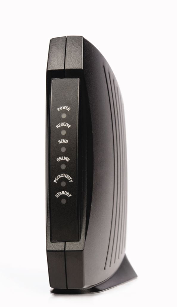
- Business equipment, including network routers/servers
- Defense electronics, e.g., radio and navigation systems
- Automotive electronics, various electronics modules and car infotainment
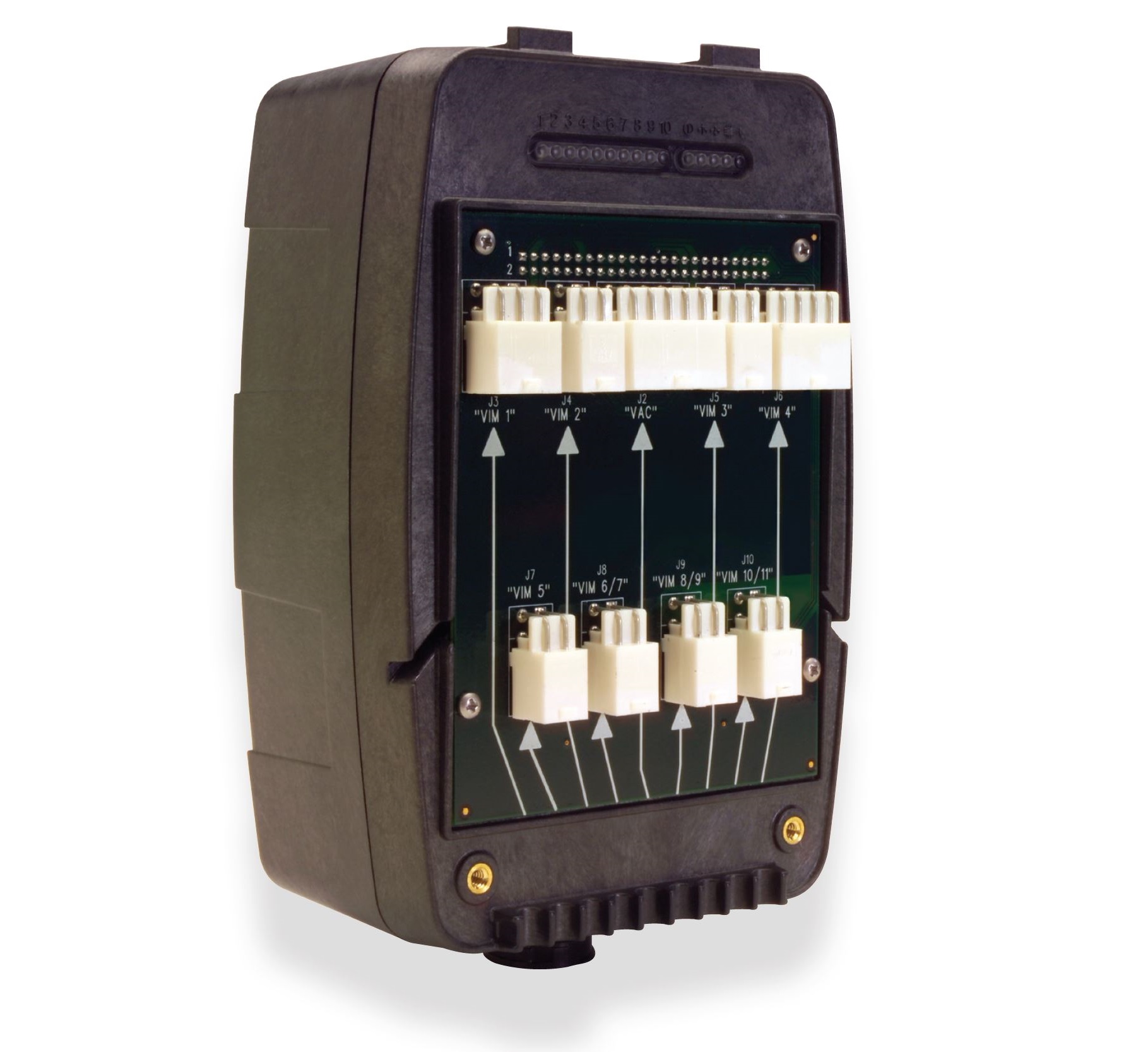
To create housings for asset tracking devices, a US-based manufacturer had long used fire-retardant PC with copper/ nickel metallization for EMI shielding.
- The OEM requirements were typical for this sort of device
- EMI shielding to meet EMC requirements of FCC part 15 Class B
- low temperature ductility
- UL 94 v-0 Fr
- low surface resistivity
To improve the customer’s bottom line, SABIC suggested LNP™ FARADEX™ DS0036IP compound a one-shot shielding solution with up to 40dB of shielding effectiveness. This product, built on LEXAN™ EXL resin, offers exceptional low-temperature impact.
This grade not only fit the molder’s existing tooling, but also eliminated the metallization step – reducing enclosure costs. In addition, the grade’s non- brominated, non-chlorinated flame-retardant system technology opened access to Eu markets.
EXCEPTIONAL PROPERTIES
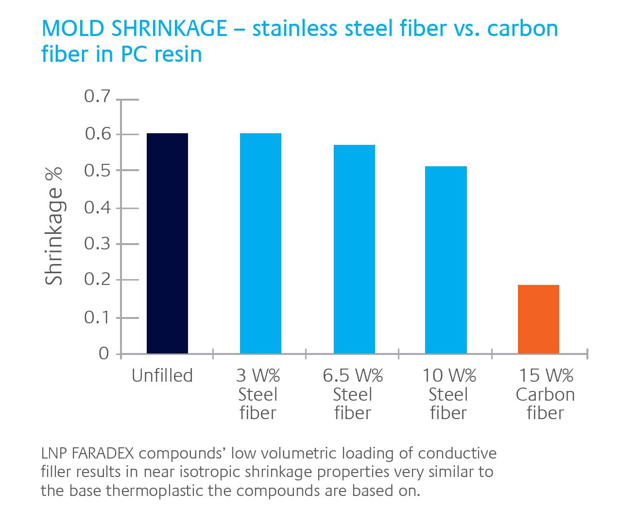
The LNP™ FARADEX™ product line from SABIC is available fully compounded with 1-2% volume stainless steel fibers in pre-colored granules. For the amorphous base resins, the compound is based on the well-known PC based copolymer proprietary technology, combined with outstanding flame retarding performance. For semi-crystalline base resins, the product is based on PP and PPA resins.
The strengths of the SABIC resin technologies, combined with advanced compounding know-how leads to a unique value offering for our customers.
The LNP™ FARADEX™ compounds product portfolio is continuously evolving and changes as customers express their desire for specialty compounds meeting more stringent requirements into today's electronics world.

The optimally dispersed conductive fibers in the polymer matrix form a mesh that, through its bulk electrical conductivity, creates a Faraday Cage effect and provides EMI shielding performance. In many applications, a welcome side effect is the low surface resistivity achieved with LNP™ FARADEX™ compounds providing excellent protection against electrical discharge (ESD).
That performance comes with the principal advantages that set LNP™ FARADEX™ compounds apart.
DESIGN FREEDOM
The complex geometries of many devices require materials with optimal moldability. LNP™ FARADEX™ compounds work efficiently with injection molding equipment, filling even small seams and openings in a way metal cannot match. This design freedom gives opportunities for further component integration/part consolidation in a mass production environment.
LIGHT WEIGHT
Shielding components made from LNP™ FARADEX™ compounds are typically 40-70% lighter than their metal counterparts.
COST SAVINGS
By eliminating processing steps, which are essential to other shielding approaches, LNP™ FARADEX™ compounds streamline your operations, potentially generating cost savings.
EASE OF PROCESSING
no electroplating, painting or metallization is required to create the shielding effect. This not only eliminates certain traditional challenges, like the difficulty of coating some thermoplastics, but also brings parts made from LNP™ FARADEX™ compounds in compliance with stringent environmental requirements covering recyclability and disposal.
COLORABILITY
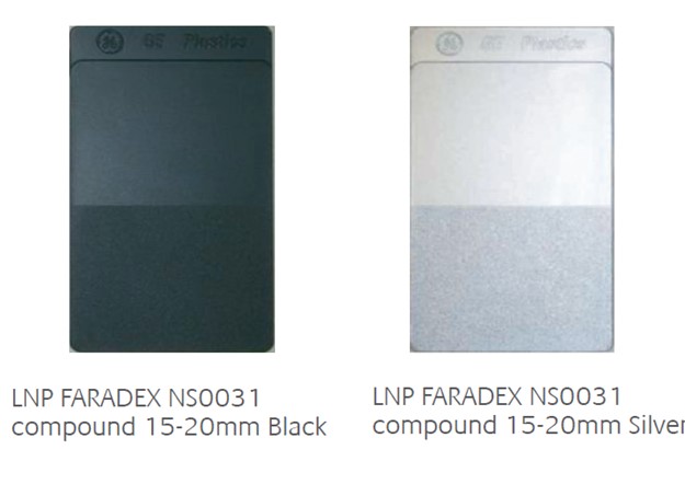
LNP™ FARADEX™ compounds can be custom-colored, thus secondary finishing steps can be eliminated. LNP™ FARADEX™ compounds come fully compounded and pre-colored in a broad range of base polymers,
enhancing their versatility – and your design freedom – even further.
SECONDARY OPERATIONS
With their conductive fillers, LNP™ FARADEX™ compounds from SABIC need no secondary operations to deliver electromagnetic shielding performance. however, other operations may be necessary to add aesthetic value or complete the manufacture of your end product.
LNP™ FARADEX™ compound products can be used with a variety of conventional plastics joining methods, including:
- Ultrasonic welding
- hot staking
- Adhesive bonding
- Mechanical assembly (including snap fits and mechanical fasteners)
- laser ablation
you can take advantage of these joining methods to improve their design for assembly and/or disassembly. For more details on these joining methods, see the SABIC Engineering Thermoplastics Design guide.
DESIGN CONSIDERATIONS
Design assistance from the start is one of the offerings of SABIC to its customers, and can help to accurately portray how lnP FArADEx compounds can operate in a customer's application. Use the following guidelines to resolve these challenges and to make the most of what LNP™ FARADEX™ compounds offer.
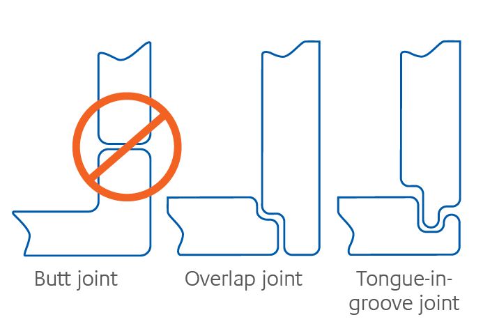
JOINT DESIGN
Ideally, joints should maintain electrical continuity to avoid acting as “slot antenna” that leak electromagnetic radiation. Unfortunately, the resin rich surface is reducing the electrical conductivity across the joint. To minimize this “slot antenna” effect, using a tongue-in-groove, or lap joint design should be used. Such designs increase the joint surface area and contact pressure, improving electrical continuity across the joint and reducing the capacity impedance. Overlap length of 1.5 to 2.5 x wall thickness should be sufficient. An environmentally responsible method to improve the electrical contact between joining surfaces is laser ablation. This technique brings stainless steel fibers to the surface based on evaporation of the resin rich skin on a molded part, using high intensity, nanosecond laser pulses.
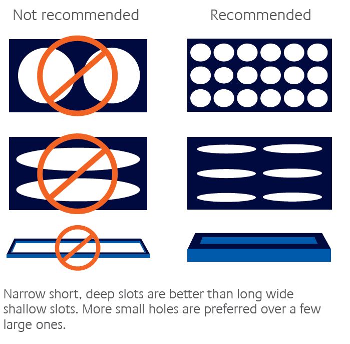
APERTURE DESIGN
The size of vent and access holes has substantial impact on electromagnetic radiation leakage. narrow, short, deep slots deliver better performance than long, wide, shallow slots. Provided the electromagnetic field direction is known the slots are best placed perpendicular. Similarly, the use of many smaller holes minimizes the disruption of induced current flows in the shield, and reduces escape and ingress of electromagnetic waves better than a large hole of the same area. Typical sizes are in the range below λ/6 (λ = wavelength).
WALL THICKNESS
Recommended wall thickness is a minimum of 1.5 mm and as uniform as possible. This allows adequate formation of the conductive network in the polymer matrix and helps minimize fiber attrition. Consider generous radii when designing corners, to minimize fiber attrition during filling phase of the mold cavity, thus preserving the shielding performance. For similar reasons, transition in wall thickness should be gradual.
BOSSES, RIBS AND GUSSETS
LNP FARADEX compound products have the right balance of mechanical properties and flow characteristics, allowing them to form complex features such as ribs, gussets and bosses. When properly designed such features can significantly improve part stiffness, strength and stability and improve design for assembly.
Design bosses and ribs following design standards for plastic materials to minimize sinking and void formation. For details, see the SABIC Engineering Thermoplastics Design Guide.
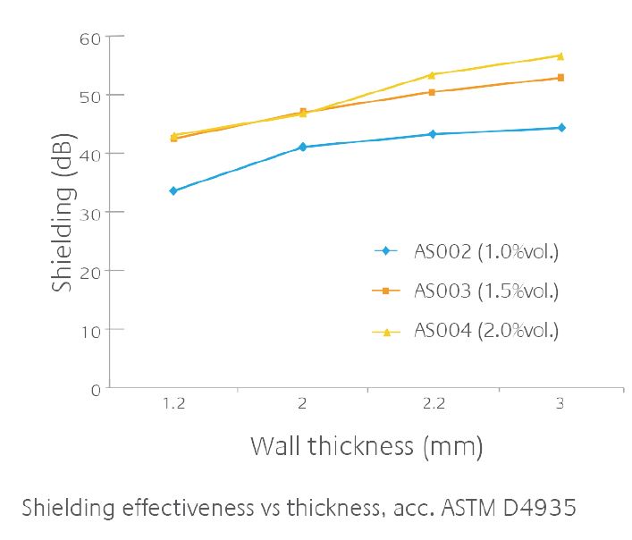
LNP™ FARADEX™ COMPOUND - SHIELDING VS. THICKNESS
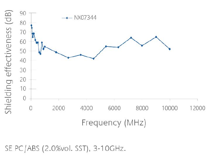
SHIELDING EFFECTIVENESS CURVE FOR FARADEX™ NX07344
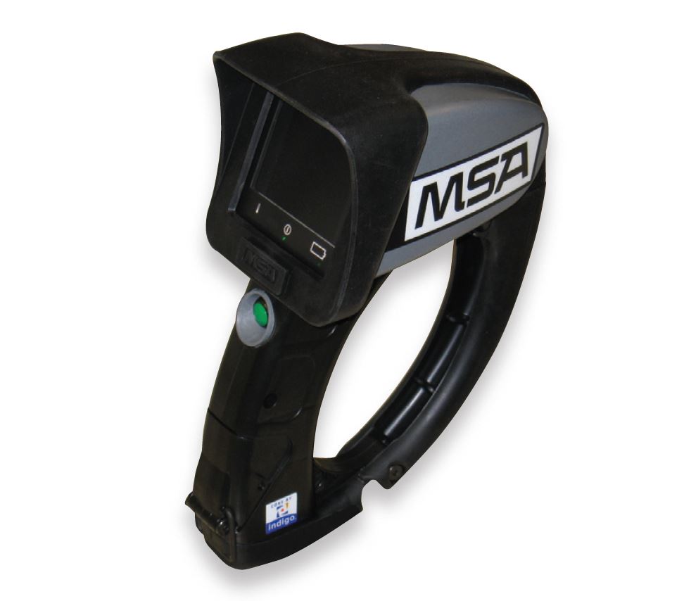
When MSA, a leading OEM of portable thermographic imaging equipment, aimed to enhance the robustness and reliability of their newest design, they turned to LNP™ FARADEX™ compounds. Specific performance requirements that the housing needed to support included:
- Pass IEC 60529 I.P. 67, for ingress and immersion
- Withstand a 6' (1.8 m) drop impact test from -40°C to +40°C
- Meet EMC requirements per CE/ EN 50081-2:1992, EN 50082-2, FCC Part 15
- Pass Direct Flame/ Heat Exposure per NFPA 1901-1 2, 1.7
LNP™ FARADEX™ DS0036IP compound was the answer, delivering the right balance of EMI shielding, mechanical, thermal and fire-retardant properties to meet the requirements above while allowing MSA to eliminate a costly and time-consuming metallization process previously used to support the EMC requirements.
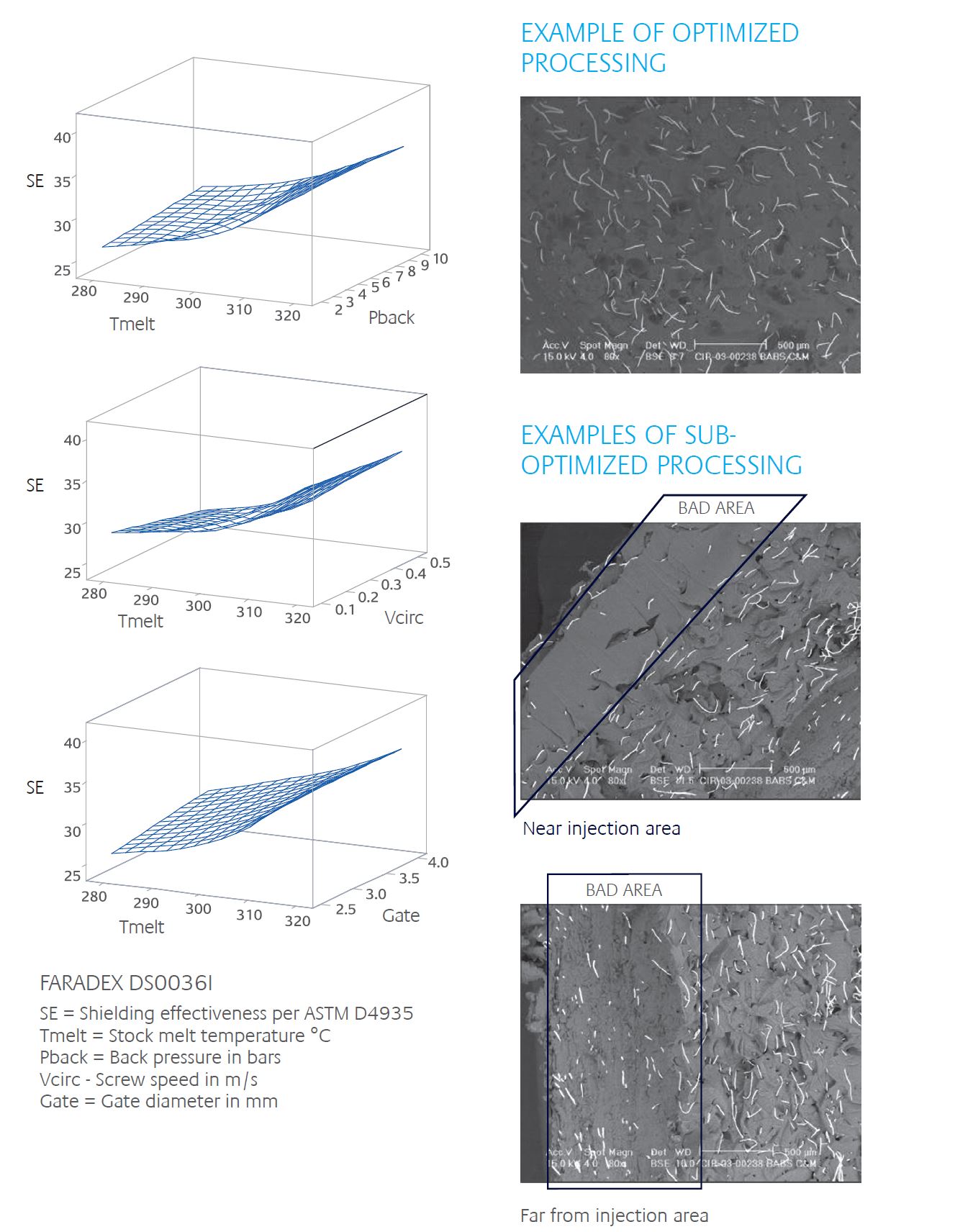
PROCESSING GUIDELINES
SABIC's LNP™ FARADEX™ compounds can be processed using standard injection molding equipment with conventional screw and nozzle design. The key to processing LNP™ FARADEX™ compound products is to minimize fiber a trition while maximizing the uniform dispersion of the fibers during plasticizing, filling and forming.
- This is key to creating the Faraday cage effect and critical to achieving the bulk conductivity essential for optimum shielding effectiveness. The following equipment guidelines and processing conditions will yield the best results
- Use a general-purpose screw with a compression ratio at a maximum of 2.5:1.
- Use a “free flow” screw tip to reduce fiber breakage.
- Do not use mixing screws.
- remove hopper magnets, which could disrupt pellet flow and feed.
- Use lower back pressure; less than or equal to 50 psi/344 kPa and low screw rotation during recovery, typically between 30 and 60 rpm.
- A shot size between 40 to 70 % of the barrel capacity is recommended to ensure an optimal residence time.
- Use higher melt temperature minimizing viscosity, while optimizing fiber attrition and improving surface finish.
- In addition a slow to medium injection speed will minimize shear and therefore fiber breakage. For optimized fiber distribution throughout the part consider to use stepped injection profile.
- Mold temperatures are preferably set relatively high to minimize shear between melt and cavity and improve surface appearance.
SPRUES, RUNNERS, GATING
Best practices to minimize fiber attrition are seen when sprue bushings and full round tool runner systems with generous dimensions and no sharp corners are used. This will also help to minimize pressure drop through the gating systems, provided low shear gating systems are considered. For LNP™ FARADEX™ compounds we advise the use of minimum 1.8 mm gate openings; pinpoint gating is because of high shear forces during filling not recommended. Hot runner systems can be used, provided they are externally heated with open nozzles, or equipped with needle shut-off valves. Torpedo-shaped hot runners should not be used in combination with LNP™ FARADEX™, as fiber attrition will be very high and EMI shielding effectiveness will suffer.
For specific recommendations on gating designs and sizing, please contact your local SABIC Technical Service Engineer.
REGRIND USAGE
Although LNP™ FARADEX™ compounds can be recycled and reprocessed, care must be taken when incorporating regrind. Sprue regrind can be used to a level of 5 %. larger quantities will lead to reducing shielding effectiveness in the molded parts, due to too high fiber attrition resulting from additional stainless steel fiber breakage during reprocessing step.
Customers should always conduct their individual, application related regrind studies to confirm EMI shielding performance.
TOOL MATERIALS
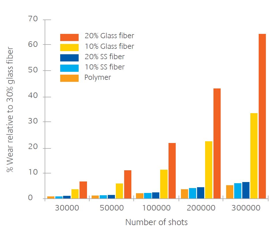
Generally for engineering resins and LNP™ FARADEX™ compounds a hardened tool steel, like 1.2344/1.2738, or h-13, is recommended. The effect of stainless steel fibers on tool wear is minimal, similar to the unfilled base polymer. E.g. glass fibers are found more abrasive than stainless steel fibers.
The hardness for stainless steel is approximately 4.4 Mohs. Typical hardness of many other fillers and additives used in thermoplastic compounds is in the range of 3.5 to 5.5 Mohs. The volumetric loading of stainless steel fibers in LNP™ FARADEX™ compounds is low. Additionally the very high aspect ratio of the stainless steel fibers ensures there are fewer abrasive fiber ends present in the compound.
Predictive wear results of LNP™ FARADEX™ compounds versus other reinforced and unfilled thermoplastic materials are shown in the table below. Processing stainless steel fiber filled compounds does not result in significant wear on tooling, or molding equipment.
IMPACT ON TOOLING AND INJECTION MOLDING EQUIPMENT
Excessive wear on tooling and molding equipment is prevented by the softness and flexibility of the stainless steel fibers. The graph on the left compares LNP™ FARADEX™ compounds with unfilled and glass fiber filled resins up to 300,000 cycles.
REGULATORY COMPLIANCE
Electromagnetic compatibility (EMC) IS the SUBJECT OF numerous standards, both National and international
The standards require performance in three ways
- Emission standards, which define maximum levels for each device category
- Immunity standards, which define performance requirements for products when exposed to EMI
- ESD/ETF standards which define performance regarding Electrical Fast Transients (EFT)/Electrostatic Discharge (ESD)
While the United States (Federal Communications Commission (FCC)) and European Union (IEC, CISPr) have their own emission and immunity standards, the World Trade Organization has obliged member countries to adopt international standards, wherever possible.
In EMC, these standards come primarily from the International Electrotechnical Commission (IEC) and the International Special Committee on Radio Interference (CISPr). IEC standards include
- IEC 61000-1 – Introduction, terms and conditions
- IEC 61000-2 – Classification of electromagnetic environments
- IEC 61000-3 – limits and disturbance levels
- IEC 61000-4 – Testing and measurement techniques
- IEC 61000-5 – Installation and mitigation guidelines
- IEC 61000-6 – generic standards
Efforts continue to harmonize and/or adopt international standards, as current standards share similarities but are not 100% equivalent.
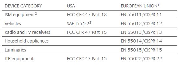
A SUMMARY OF DEVICE CLASSIFICATIONS AND THEIR APPLICABLE ELECTROMAGNETIC COMPATIBILITY (EMC) STANDARDS IN THE U.S.A. AND EU
- European and U.S. standards share similarities, though they are not equivalent.
- The FDA and their Center for Devices and radiological health (CDhr) encourage device manufacturers to use IEC 60601-1-2 (medical equipment, electromagnetic compatibility requirements and tests) as their EMC standard, which includes limits for both emission and immunity.
- SAE standards are self-imposed by the Automotive Industry through agreement with the FCC.
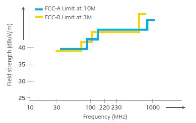
FCC REGULATIONS
The Federal Communications Commission (FCC) has its own set of EMC standards. Under these standards, a digital device is defined as an “unintentional radiator that generates and uses digital timing signals operating at > 9Khz.”
These are categorized in two classes
- Class A, for industrial and commercial (central office) equipment (allowing for EMC testing at 10 meters)
- Class B, for use anywhere, especially residential environments (testing at 3 meters).
A COMPARISON OF EMISSION LIMITS FOR FCC REGULATED ASSEMBLED DIGITAL DEVICES
(i.e., ISM, radio and Tv receivers class B devices, ITE class A devices)
SHIELDING EFFECTIVENESS TEST METHODS
During the application development phase EMC testing is needed to identify the sources of electromagnetic energy emitted from an electronic device in an effort to reduce potential interference to other equipment, as well as determine the susceptibility of the equipment from electromagnetic energy emitted from other sources nearby.
Such EMC test provides evidence that your product complies with the relevant EMC regulations and directives. Testing also highlights potential issues, preferably already during the development phase, thus allowing to fix the problem before production.
Completed products shall be tested on performance and reliability in an anechoic chamber. Specialized agencies can provide the necessary testing and evaluation services, when EMC testing capability is not part of your organization.
Other test methods may be more accessible and may also be a tool for your quality control needs.
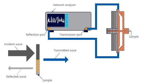
ASTM D4935
STANDARD TEST METHOD FOR MEASURING THE ELECTROMAGNETIC SHIELDING EFFECTIVENESS OF PLANAR MATERIALS
Although no longer actively maintained, ASTM D4935 is a sound standard for far field shielding effectiveness testing and shows good precision, accuracy and reproducibility. This method is well suited for heterogeneous materials and reports SE of a material in a planar configuration, exposed to a far field electromagnetic wave. Typically, measurements are taken over a frequency range of 30Mhz.–1.5ghz. This method is suitable for various materials and is useful for product development and evaluating the performance of different shield materials and different shield thicknesses.
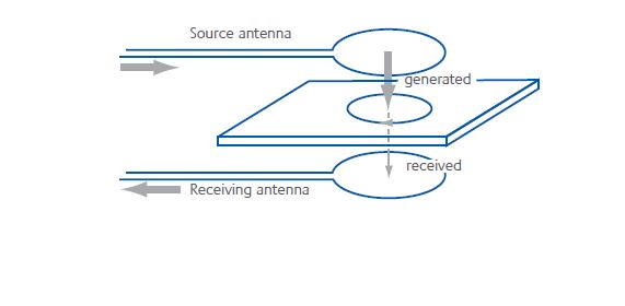
EDDY-CURRENT METHOD
A two-probe method that determines the “Square resistance” (rs) of a sample by generating an h-field and measuring the attenuated h-field with the receiving antenna (see figure). The induced current in the sample is a direct measure of rs.
Knowing rs, Shielding Effectiveness (under far field conditions, i.e., shield > l/2π from source) can be calculated SE = 20*log (1+188.5/rs).
KEY BENEFITS
- Method is non-destructive
- The measurement is fast (15 sec.) and requires no sample preparation
- Eddy-Current Method shows good correlation with standardized method (ASTM D4935)
- Method does not require flat surfaces, so it is suitable for application testing
- Equipment is mobile, so it can be used at injection molding trials
- An effective way to monitor Shielding Effectiveness as a quality assurance tool or for application development
TEST METHODS FOR ESD PROTECTION
- Surface resistivity (IEC 93, ASTM D257, ASTM D4496)
- Measures of the ability to conduct an electrical current across a surface
- Typical performance Sr < 1012 Ω/sq
Static decay (IEC 61000-4-2, FTMS101B, Mil-B-81750B)
- Measure of the ability to discharge a specified electro static load
- Typical requirement is bleed-off time from 5000v to 0v in less than 2 seconds at 23°C and 15% rh (relative humidity)
COMMITTED TO SUSTAINABILITY
SABIC has made sustainability a central aspect of its business strategy, with two key focus areas.
First, SABIC is focused on continuously reducing the intensity of our global operational footprint, including reducing carbon intensity, improving energy and water use, and increasing material efficiency – benefits that also ultimately flow to our customers.
To this end, SABIC embraces Responsible Care®, the chemical industry’s global voluntary initiative to continuously improve safety, health, and environmental performance, as a framework for sustainability. We are building upon our strong management systems and history of responsible manufacturing to create an even safer, cleaner environment.
Second, our sustainability program focuses on the marketplace, where we are committed to sharing our expertise and working even more closely with our customers to develop products, applications and solutions that respond to their sustainability needs. Our product portfolio, coupled with our technological expertise and history of innovation, gives us the opportunity to develop materials that can help our customers tackle a wide variety of environmental issues.
“We commend SABIC for its proactive efforts to provide new alternatives to traditional materials across the spectrum of sustainability. The key to this initiative is the verification of environmental benefits using established standards and rigorous validation and testing processes. Our work in independently evaluating SABIC’s materials helps ensure that they fulfill their eco claims and deliver proven, measurable value to customers.”
Truman Semans, Principal, greenOrder

SUSTAINABILITY SOLUTIONS PORTFOLIO
The Sustainability Solutions portfolio makes it easy for customers to identify, evaluate and select the right SABIC materials. This portfolio encompasses five broad categories that address today’s most important environmental initiatives:
- Post-consumer recycled (PCr) content
- Automotive weight-out
- Advanced flame retardance
- Energy efficiency
- Bio-based materials
The properties, performance and/or content of these materials can make a significant contribution to reduced environmental impact, from lowering carbon emissions to maximizing use of the earth’s limited resources.
To support our customers’ environmental objectives, SABIC plans to expand the Sustainability Solutions portfolio as we innovate in new technologies, improve our manufacturing processes and develop a deeper understanding of how our products and their uses contribute to sustainability.
VALIDATING SUSTAINABILITY CLAIMS
Products and applications in the SABIC Sustainability Solutions portfolio are validated in two potential ways: either they meet one or more widely recognized third-party sustainability standards, or their environmental benefits relative to incumbent technologies have been verified using the company’s new Sustainable Product Scorecard.
For a significant number of products in the portfolio, there are third-party standards defining sustainability features, such as halogen-free flame retardance or post-consumer recycled content.
For a number of other solutions, such as automotive lightweight design or footprint reductions, there are no widely recognized industry or third- party standards defining sustainability. For these solutions, it is necessary to verify the environmental benefits over incumbent alternatives using life Cycle Assessment (lCA) methods for estimating the environmental footprint of products and processes. SABIC incorporated these LCA methods into its new Sustainable Product Scorecard to ensure that the verification process is done in a rigorous and credible way.
This scorecard has two components:
LIFE CYCLE ASSESSMENT
LCA and life Cycle Inventory (LCI) methodologies, based on the ISO 14040 and ISO 14044 standards, are used to build the first component of the scorecard. The carbon and energy footprints of the products or applications are estimated across the life cycle. The results of the assessment are summarized in the Environmental Product Datasheet.
GREEN CHEMISTRY SCREEN (GCS)
This component of the scorecard guides the assessment of the chemical composition of the product, including impurities, byproducts and catalysts, against well-established toxicological, regulatory and industry standard criteria.
The output of the scorecard is used to develop well-substantiated environmental claims that undergo third-party verification. These validated claims enable our customers to differentiate their products and showcase the results of their sustainability efforts.
SUSTAINABLE STANDARDS FOR ELECTRONIC DEVICES
SABIC is dedicated to global sustainability initiatives and working with customers to help resolve tough environmental challenges.
SABIC develops and manufactures thermoplastics that meet global standards for production and recyclability. Key focus areas are the requirements of halogen-free parts, helping to reduce environmentally harmful substances and emissions, conserving water resources and promoting energy efficiency.
Environmental standards for electronic devices are covered under two broad standards:
RESTRICTION OF HAZARDOUS SUBSTANCES (ROHS)
This EU legislation requires the elimination of lead, cadmium, mercury, hexavalent chromium, polybrominated biphenyl (PBB) and certain polybrominated diphenyl ether (PBDE) flame retardants.
WASTE FROM ELECTRICAL AND ELECTRONIC EQUIPMENT (WEEE)
The WEEE standard raises the required recycling level for electrical and electronic equipment. hardware manufacturers are responsible for recycling costs at the end of the devices’ life.
LNP FARADEX COMPOUNDS CAN HELP
All LNP™ FARADEX™ compounds are RohS compliant, and grades based on non- brominated, non chlorinated flame retardant systems are available.
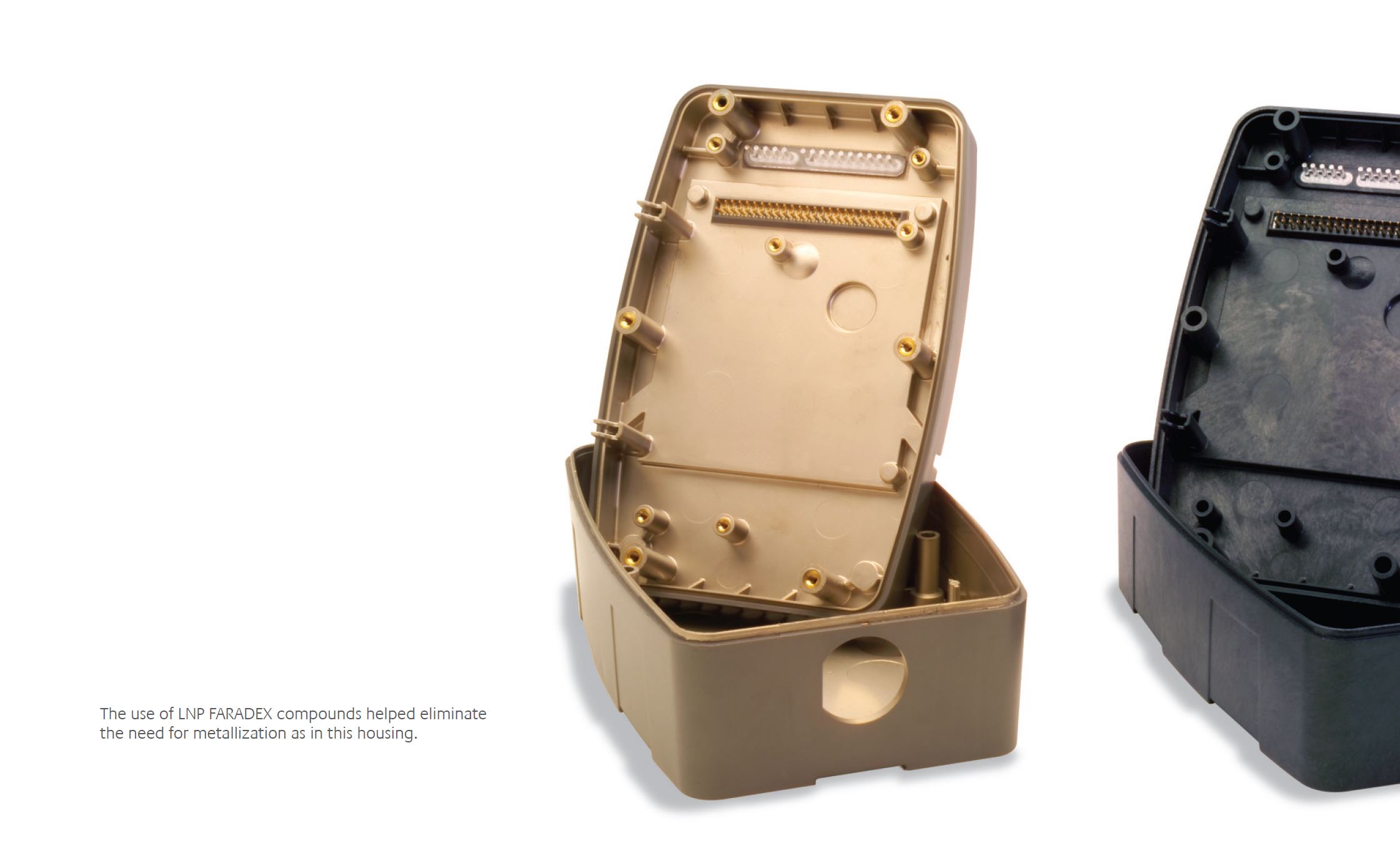
Furthermore, because LNP™ FARADEX™ grades are available in precolored versions, they can eliminate the need for metallization and/or conductive paint treatments. lnP FArADEx compounds therefore offer OEms the potential to eliminate volatile organic compounds (vOCs) emitted by these coating processes. Such processes have shown to negatively impact air quality. Using LNP™ FARADEX™ compounds can help manufacturers increase overall productivity by eliminating the painting/plating step, minimizing or eliminating costs from emission- permitting and disposal fees, all while providing an effective EMI shielding solution. At the end of their life cycle, they can be recycled without the need to have paints or plating removed.
LNP FARADEX COMPOUNDS: ENVIRONMENTAL PRODUCT DECLARATION
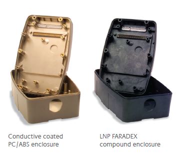
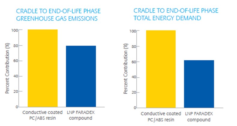
LNP FARADEX COMPOUND VERSUS CONDUCTIVE COATED PC/ABS RESIN

The following benefits are applicable to LNP™ FARADEX™ compound versus conductive coated PC/ABS resin:
PROCESS ELIMINATION
LNP™ FARADEX™ compounds deliver similar performance without the need of a secondary, conductive painting process, which is required when using a standard PC/ABS resin. This eliminates associated volatile organic compound (VOC) emissions and permit fees, and increases overall productivity.
GREENHOUSE GAS EMISSIONS
On a component basis, LNP™ FARADEX™ compounds have significantly lower GHG emissions compared to conductive painted PC/ABS resin over the full product life.
A PCB enclosure made from LNP™ FARADEX™ compounds has a greenhouse gas footprint of 4.0 kg during its sourcing, manufacturing, fabrication, use and disposal versus 5.1 kg for one made from conductive painted PC/ABS resin, resulting in a 21% lower impact. Making 200,000 PCB enclosures with LNP™ FARADEX™ compounds instead of conductive painted PC/ABS resin could avoid as much GHG as would be absorbed annually by a UK forest the size of 117 soccer fields.
ENERGY EFFICIENCY
On a component basis, LNP™ FARADEX™ compounds have a significantly lower energy footprint compared to conductive painted PC/ABS resins over the full product life.
A PCB enclosure made from LNP™ FARADEX™ compounds consumes 72MJ of energy during its sourcing, manufacturing, fabrication, use and disposal versus 116 MJ for one made from conductive painted PC/ABS resin, resulting in a 38% lower impact. Making 200,000 PCB enclosures with LNP™ FARADEX™ compounds instead of conductive painted PC/ABS resin could save enough energy to power 708 European homes for a year.
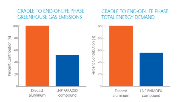
LNP FARADEX COMPOUND VERSUS DIECAST ALUMINUM ALLOY
The following benefits are applicable to LNP™ FARADEX™ compound versus aluminum alloy.
LOWER COMPONENT COSTS
LNP™ FARADEX™ compounds are capable of meeting electronics compatibility regulations and part design requirements, while reducing the overall weight by up to 50% compared to aluminum alloys used in typical automotive electronics enclosure applications. The lower mass and system costs of LNP™ FARADEX™ compounds may contribute to total cost savings
GREENHOUSE GAS EMISSIONS
On a component basis, LNP™ FARADEX™ compounds have significantly lower GHG emissions compared to aluminum alloy over the full product life.
During its sourcing, manufacturing, fabrication, use and disposal, an aluminum alloy PCB enclosure has a GHG footprint of 7.6 kg. In comparison, a similar PCB enclosure made from LNP™ FARADEX™ compounds has a GHG footprint of 4.0 kg – a 47% lower impact. Making 200,000 PCB enclosures5 with LNP™ FARADEX™ compounds instead of aluminum could avoid as much GHG as would be absorbed annually by a UK forest the size of 384 soccer fields.6
ENERGY EFFICIENCY
On a component basis, LNP™ FARADEX™ compounds have a significantly lower energy footprint to aluminum alloy over the full product life. A typical PCB enclosure made from LNP™ FARADEX™ compound consumes 72 MJ of energy during its sourcing, manufacturing, fabrication, use and disposal versus 135 MJ for one made from aluminum alloy, which results in a 46% lower impact. Making 200,000 PCB enclosures with lnP FArADEx resin instead of aluminum could save enough energy to power 1,014 European homes7 for a year.
GREEN CHEMISTRY
LNP™ FARADEX™ compounds are designed to comply with the rohS Directive (2002/95/EC), the Joint Industry guide and the IEC “halogen-free” standard (IEC 61249-2-21), and eco-labels such as Ecoflower, TCO, Blue Angel and nordic Swan. In addition, its formulation does not include any of the substances of very high concern as specified under the rEACh regulation (EC 1907/2006) as verified on Oct 31, 2011.
REFERENCES
SABIC collaborates with greenOrder, a leading sustainability consulting firm, to provide third-party technical analysis and verification of Sustainability Solutions benefit claims.
- Includes raw material extraction, manufacturing, fabrication, use and end-of-life stages
- Based on the Internal life Cycle Assessment data; see claims for greater details
- Based on Ecoinvent database
- PC, ABS life cycle data was taken from Ecoprofiles of the European Plastics Industry, www.plasticseurope.org/plastics- sustainability/eco-profiles
- Based on resin volume of 75MT/year
- Average CO2 emissions absorbed by 1 hectare of UK forest is equal to 3800 kg source: Cannell et al., Climate Change, vol. 42, number 3, pp 505-530, 1999
- Average residential power usage in the EU (year) is equal to 3500 kwh/year, www.energy.eu – Europe’s Energy Portal; gas & Electricity: Domestic
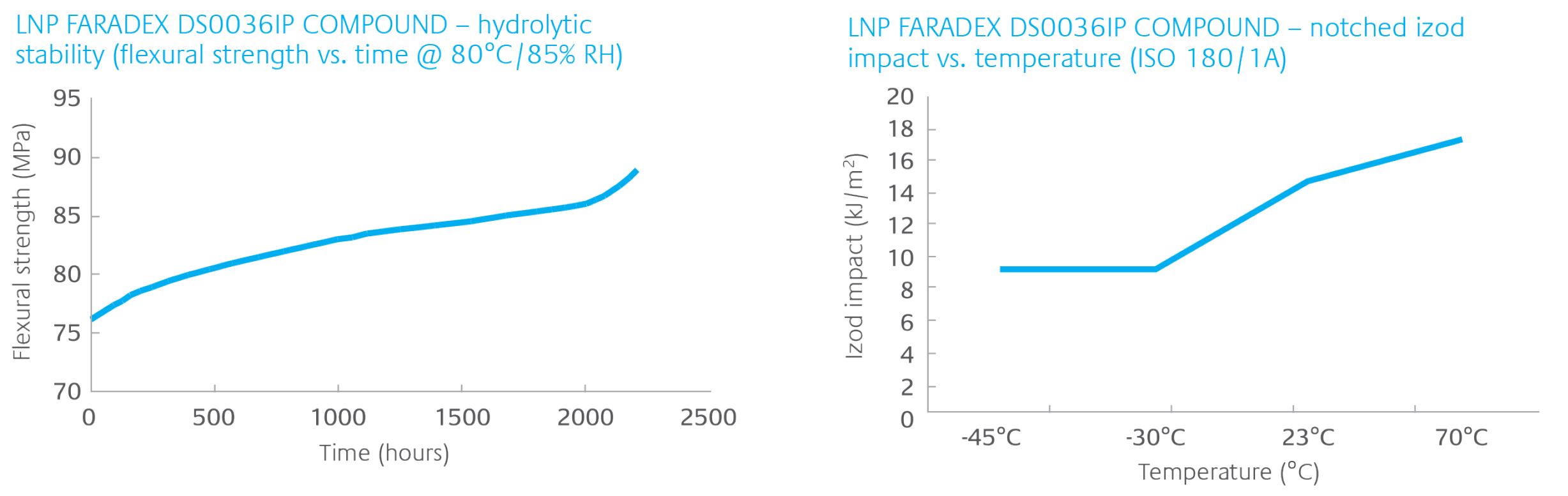
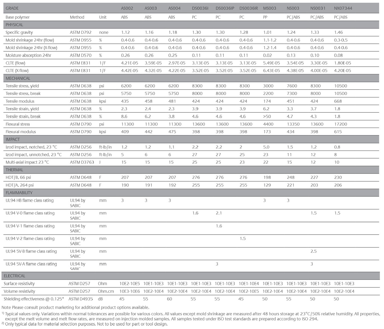
LNP FARADEX COMPOUND PROPERTY PROFILES
The charts below highlight long-term continuous performance data that SABIC conducts to characterize products and support customer application development activities
GLOBAL SUPPORT
Behind each LNP™ FARADEX™ compound stands the extensive product and application support for which SABIC is well known. By optimizing the use of materials for your specific applications, this support can help you achieve even greater design flexibility and cost savings and improve time to market with differentiated product solutions.
SABIC's Polymer Processing Development Center (PPDC) in Pittsfield, MA USA is one of the largest engineering research and development centers in the world and part of a global network of Technology and Innovation (T&I) Centers for SABIC.
The PPDC offers a range of services, from prototype development to secondary operations to help customers validate parts designs on production-scale equipment. In addition, SABIC's global T&I Centers offer anechoic chambers for EMC test and measurement capabilities, where materials and devices can be tested for compliance to EMC standards such as CISPR and FCC.
Available resources include:
- EMC test and measurement to support product and application development and compliance testing
- Performance testing for mechanical, thermal and dimensional stability
- Computer-aided engineering support
- Environmental simulation, including weathering tests and heat aging
- Regional application development and technical support
- Industrial design and concept development
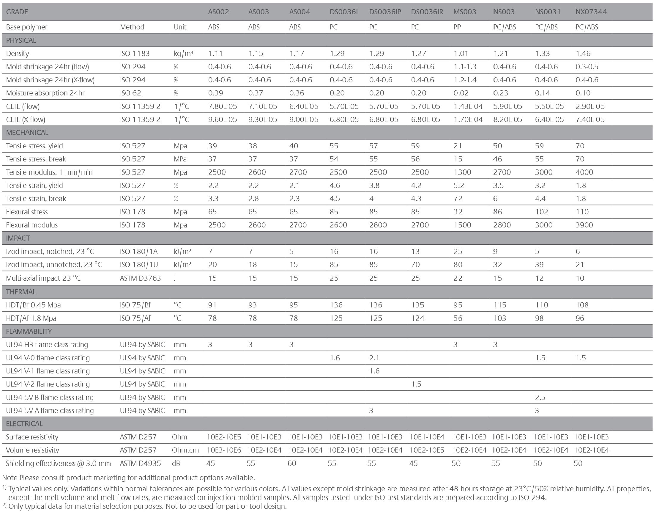
PRODUCTS AND GRADES
CONTACT US
Reach out to us for one-on-one support to ensure you have all the information and insights you need to choose the best-fit material for your application.
DISCLAIMER: THE MATERIALS, PRODUCTS AND SERVICES OF SAUDI BASIC INDUSTRIES CORPORATION (SABIC) OR ITS SUBSIDIARIES OR AFFILIATES (“SELLER”) ARE SOLD SUBJECT TO SELLER’S STANDARD CONDITIONS OF SALE, WHICH ARE AVAILABLE UPON REQUEST. INFORMATION AND RECOMMENDATIONS CONTAINED IN THIS DOCUMENT ARE GIVEN IN GOOD FAITH. HOWEVER, SELLER MAKES NO EXPRESS OR IMPLIED REPRESENTATION, WARRANTY OR GUARANTEE (i) THAT ANY RESULTS DESCRIBED IN THIS DOCUMENT WILL BE OBTAINED UNDER END-USE CONDITIONS, OR (ii) AS TO THE EFFECTIVENESS OR SAFETY OF ANY DESIGN OR APPLICATION INCORPORATING SELLER’S MATERIALS, PRODUCTS, SERVICES OR RECOMMENDATIONS. UNLESS OTHERWISE PROVIDED IN SELLER’S STANDARD CONDITIONS OF SALE, SELLER SHALL NOT BE RESPONSIBLE FOR ANY LOSS RESULTING FROM ANY USE OF ITS MATERIALS, PRODUCTS, SERVICES OR RECOMMENDATIONS DESCRIBED IN THIS DOCUMENT. Each user is responsible for making its own determination as to the suitability of Seller’s materials, products, services or recommendations for the user’s particular use through appropriate end-use and other testing and analysis. Nothing in any document or oral statement shall be deemed to alter or waive any provision of Seller’s Standard Conditions of Sale or this Disclaimer, unless it is specifically agreed to in a writing signed by Seller. Statements by Seller concerning a possible use of any material, product, service or design do not, are not intended to, and should not be construed to grant any license under any patent or other intellectual property right of Seller or as a recommendation for the use of any material, product, service or design in a manner that infringes any patent or other intellectual property right.
SABIC and brands marked with ™ are trademarks of SABIC or its subsidiaries or affiliates.
© 2023 Copyright SABIC. All rights reserved.
Your PDF is downloading. Please wait.
Register for High value Multi-Point Data
- Access validated product data to streamline material selection
- Get inspired by innovative application ideas
- Register for high value multi-point data and a personalized experience
